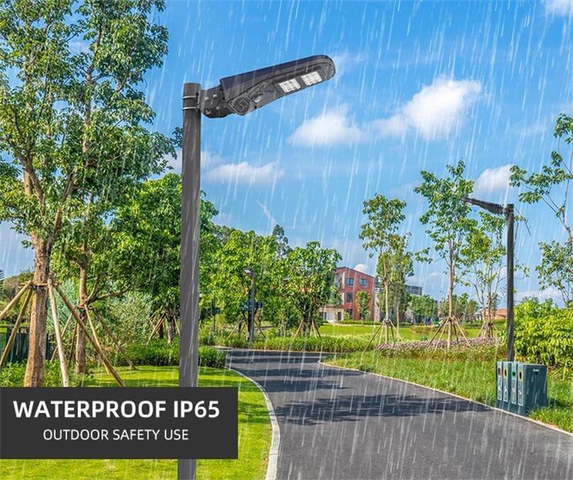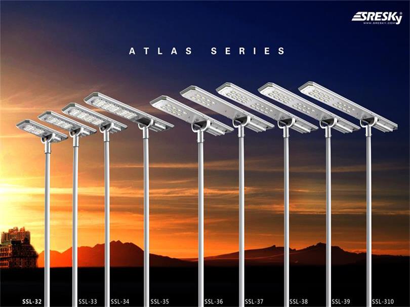
The wind resistance design of the battery component bracket and the lamp post.
Before, a friend kept asking me about the wind and pressure resistance of solar street lights. Now we might as well do the calculation.
Solar Street Lights In the solar street light system, a structurally important issue is the wind resistance design. The wind resistance design is mainly divided into two major parts, one is the wind resistance design of the battery component bracket, and the other is the wind resistance design of the lamp post.
According to the technical parameter data of battery module manufacturers, the solar cell module can withstand upwind pressure of 2700Pa. If the wind resistance coefficient is selected to be 27m/s (equivalent to a ten-level typhoon), according to non-viscous fluid mechanics, the wind pressure of the battery assembly is only 365Pa. Therefore, the component itself can withstand 27m/s wind speed without damage. Therefore, the key consideration in the design is the connection between the battery assembly bracket and the lamp post.
In the design of the solar street light system, the connection design of the battery assembly bracket and the lamp post is fixedly connected by a bolt rod.
Windproof design of street lamppost
The parameters of the solar street light are as follows:
Panel tilt angle A = 16o pole height = 5m
The solar street light manufacturer design selects the width of the welding seam at the bottom of the lamp post δ = 4mm and the outer diameter of the bottom of the lamp post = 168mm
The surface of the weld is the destruction surface of the lamp post. The distance from the calculation point P of the resistance moment W of the destruction surface of the lamp pole to the action line of the panel load F received by the lamp pole is PQ = [5000+(168+6)/tan16o]×Sin16o = 1545mm=1.545m. Therefore, the moment of wind load on the destruction surface of the lamp pole M = F × 1.545.
According to the design maximum allowable wind speed of 27m/s, the basic load of the 2×30W dual-lamp solar street light panel is 730N. Considering the safety factor of 1.3, F = 1.3×730 = 949N.
Therefore, M = F × 1.545 = 949 × 1.545 = 1466N.m.
According to mathematical derivation, the resistance moment of the circular ring-shaped failure surface W = π×(3r2δ+3rδ2+δ3).
In the above formula, r is the inner diameter of the ring and δ is the width of the ring.
Failure surface resistance moment W = π×(3r2δ+3rδ2+δ3)
=π×(3×842×4+3×84×42+43) = 88768mm3
=88.768×10⁻⁶ m3
Stress caused by wind load acting on the failure surface = M/W
= 1466/(88.768×10-6) =16.5×10⁶pa =16.5 Mpa<<215Mpa
Among them, 215 Mpa is the bending strength of Q235 steel.
Therefore, the width of the weld seam designed and selected by the solar street light manufacturer meets the requirements. As long as the welding quality can be guaranteed, the wind resistance of the lamp post is no problem.
outdoor solar light| solar led light |all in one solar light
Street light Information

The special working hours of solar street lights are affected by different working environments such as weather and environment. The service life of many street lamp bulbs will be greatly affected. Under the inspection of our relevant personnel, it has been found that the changes in street lamp energy-saving devices have a very good effect and save electricity. Obviously, the workload of maintenance workers for street lights and high pole lights in our city is greatly reduced.
Circuit principle
At present, urban road lighting sources are mainly sodium lamps and mercury lamps. The working circuit is composed of sodium lamps or mercury bulbs, inductive ballasts, and electronic triggers. The power factor is 0.45 when the compensation capacitor is not connected and is 0.90. The overall performance of the inductive load. The working principle of this solar street light power saver is to connect a suitable AC reactor in series in the power supply circuit. When the grid voltage is lower than 235V, the reactor is short-circuited and does not work; when the grid voltage is higher than 235V, the reactor is put into operation to ensure that the working voltage of the solar street light will not exceed 235V.
The whole circuit is composed of three parts: power supply, power grid voltage detection and comparison, and output actuator. The electrical schematic diagram is shown in the figure below.
The solar street landscape lighting power supply circuit is composed of transformers T1, diodes D1 to D4, three-terminal regulator U1 (7812) and other components, and outputs +12V voltage to power the control circuit.
Power grid voltage detection and comparison are made up of components such as op-amp U3 (LM324) and U2 (TL431). The grid voltage is stepped down by resistor R9, D5 is half-wave rectified. C5 is filtered, and a DC voltage of about 7V is obtained as the sampling detection voltage. The sampled detection voltage is filtered by a low-pass filter composed of U3B (LM324) and sent to the comparator U3D (LM324) for comparison with the reference voltage. The reference voltage of the comparator is provided by the voltage reference source U2 (TL431). Potentiometer VR1 is used to adjust the amplitude of the sampling detection voltage, and VR2 is used to adjust the reference voltage.
The output actuator is composed of relays RL1 and RL3, high-current aviation contactor RL2, AC reactor L1 and so on. When the grid voltage is lower than 235V, the comparator U3D outputs a low level, the three-tube Q1 is turned off, the relay RL1 is released, its normally closed contact is connected to the power supply circuit of the aviation contactor RL2, RL2 is attracted, and the reactor L1 is short-circuited Not working; when the grid voltage is higher than 235V, the comparator U3D outputs a high level, the three-tube Q1 is turned on, the relay RL1 pulls in, its normally closed contact disconnects the power supply circuit of the aviation contactor RL2, and RL2 is released.

Reactor L1 is connected to the solar street light power supply circuit, and the excessively high grid voltage is part of it to ensure that the working voltage of the solar street light will not exceed 235V. The LED1 is used to indicate the working state of the relay RL1. The LED2 is used to indicate the working state of the aviation contactor RL2, and the varistor MY1 is used to extinguish the contact.
The role of the relay RL3 is to reduce the power consumption of the aviation contactor RL2, because the RL2 startup coil resistance is only 4Ω, and the coil resistance is maintained at about 70Ω. When DC 24V is added, the startup current is 6A, and the maintenance current is also greater than 300mA. The relay RL3 switches the aviation contact RL2’s coil voltage reducing the holding power consumption.
The principle is: when RL2 starts, its normally closed auxiliary contact shorts the coil of relay RL3, RL3 is released, and the normally closed contact connects the high voltage terminal 28V of transformer T1 to the bridge rectifier input of RL2; after RL2 starts, its The normally closed auxiliary contact is opened, and the relay RL3 is electrically attracted. The normally open contact connects the low voltage terminal 14V of the transformer T1 to the bridge rectification input terminal of RL2 and maintains the aviation contractor with 50% of the starting coil voltage RL2 pull-in state
Table of Contents